A teflon check valve earns attention where fluids are corrosive, cleanability matters, and reverse flow cannot be ignored. Its fluoropolymer wetted surfaces can resist many aggressive chemicals, while the valve’s simple purpose remains familiar: let fluid move forward and close when flow reverses. Small details matter. A sticking disc, unsuitable seal, or incorrect pressure rating can still cause trouble.
The wider market signals why valve selection deserves care. Grand View Research valued the global industrial valves market at USD 78.3 billion in 2023 and forecast 4.9% annual growth from 2024 to 2030. That figure covers many valve types, not Teflon check valves specifically. It is useful context, not proof that one material suits every process. Temperature, pressure, media compatibility, installation position, and maintenance access should guide the decision. A clear datasheet helps. A guess does not.
One source limitation matters: no article or verifiable named-expert quotation was supplied, so I cannot responsibly invent an expert’s name or words. A practical design principle, however, is worth keeping in view: “Choose the valve for the actual process conditions, not the material name alone.” Treat that as guidance, not an attributed quotation. Even PTFE has limits. Review manufacturer compatibility charts and pressure-temperature ratings before specifying a unit. Then compare cracking pressure, connection style, and service needs. The right choice is rarely dramatic. It is the valve that keeps working when the line gets difficult.
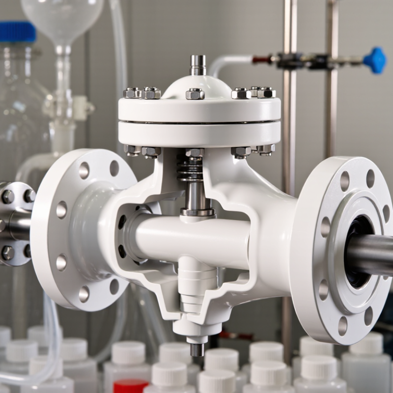
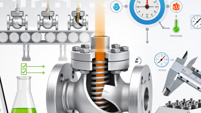
A Teflon check valve allows fluid to move in one direction and helps prevent it from flowing backward. When upstream pressure rises above downstream pressure, the valve opens. If flow reverses, the closing element returns to its seat. The result is a simple, automatic barrier. No manual handle is needed.
In a small chemical dosing line, for example, a check valve can help stop liquid from draining back toward a supply tank when a pump stops. PTFE components are valued for broad chemical resistance and a smooth surface, but “Teflon” does not mean suitable for every fluid or condition. Check the valve’s material specifications, pressure range, temperature limits, and installation orientation. A mismatch can lead to wear or poor sealing.
Reverse-flow prevention is not the same as guaranteed, leak-free isolation. Particles, damaged seats, or low closing pressure may allow some leakage. That matters. I would also avoid choosing a valve by material name alone; connection size and flow requirements affect performance. A clear review of the fluid and operating conditions makes the one-way protection more dependable.
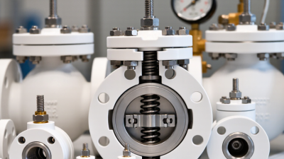
A Teflon check valve relies on several small parts working together. PTFE sealing surfaces help limit leakage when the valve closes. They also resist many corrosive fluids, though compatibility depends on the exact chemical, concentration, and temperature. A material chart is useful, but it cannot replace checking actual operating conditions.
The seat provides the contact surface for the moving disc. When flow pushes the disc open, fluid passes through; when flow falls or reverses, the disc returns to the seat. That movement should be smooth. A scratched seat, trapped grit, or a disc that sticks can prevent a tight seal. Small details matter.
PTFE is relatively soft compared with many metals. This helps it conform to the seating face, but excessive pressure or heat can cause deformation or wear. The valve’s pressure range, flow direction, and installation position should therefore match the system design. A careful inspection can reveal uneven wear before leakage becomes obvious. Still, I would not assume that a low-friction seal solves every problem; poor sizing can cause chatter and shorten component life.
A PTFE check valve can suit corrosive or high-purity service because the material resists many chemicals and has a smooth, low-friction surface. But “near 260°C” is a typical upper temperature reference, not a universal operating promise. Formulation, valve design, pressure, and exposure time all affect performance.
That matters. Near its upper temperature range, PTFE can soften and deform under load. In a check valve, that may affect the sealing surfaces, closing action, or long-term leakage rate. Pressure and repeated temperature cycling can make the practical limit lower than the material rating suggests. Not a guarantee.
I would treat 260°C as a boundary to verify, not a routine set point. Check the manufacturer’s temperature-pressure data for the exact valve, and consider the hottest local temperature, not only the process average. A brief heat spike may still matter. Confirm compatibility with the fluid and review pressure, cycling, and expected service life together. If those details are unclear, the rating alone is not enough to choose safely.
A PTFE check valve’s performance is best judged from test data, not material claims alone. Cracking pressure is the inlet pressure needed to open the valve and start flow. A low value may suit gravity-fed lines, while a higher value can help prevent unwanted opening. Check whether the stated figure was measured with air or liquid, and at what temperature. Test conditions matter. Small details do.
Flow capacity shows how much fluid passes at a given pressure difference. Compare the published flow curve with your expected flow rate, fluid viscosity, and pipe size. Pressure drop is the resistance the valve adds once open; excessive loss can reduce downstream pressure or increase pump demand. In practical sizing, look for data at several flow rates rather than one maximum figure. A compact valve may perform differently from a larger one, even with similar connection sizes. Results can vary. If the datasheet leaves test conditions unclear, ask for clarification or verify performance in a controlled setup. A neat specification table is useful, but it is not the whole story.
Why Choose a Teflon Check Valve?
Chemical compatibility is the first selection check, but “Teflon” alone is not a complete specification. Confirm the wetted materials, including the body lining, disc, seals, and spring. Concentration, temperature, and exposure time can change performance. ASTM D543-21 describes methods for evaluating plastics exposed to chemical reagents; it does not certify every valve for every fluid. Check test conditions against your process. Compatibility charts are useful, but only as a starting point.
Pressure ratings need equal care. Compare the valve’s rated pressure at operating temperature, not just its nominal size or cold-water rating. Include differential pressure, startup surges, and the pressure required for the check valve to open. Small details matter. Ask for the pressure-temperature limits and test records for the complete assembly, since the lining and seals may set the practical limit.
ISO 5208:2015 specifies pressure-testing procedures and leakage-rate classes for industrial valves; Rate A means no visually detectable leakage under the stated test conditions. That result does not guarantee performance in every installation. Review the certificate for test pressure, medium, duration, and acceptance class, and confirm that the procedure covers the valve’s closure direction. One detail is easy to miss: a successful factory test cannot replace checking real service conditions.
| Selection Check | Practical Data | What to Verify |
|---|---|---|
| Chemical compatibility | PTFE generally offers broad resistance to many acids, bases, and solvents at ambient conditions. Compatibility can change with concentration, temperature, pressure, and exposure time. | Check the exact chemical, concentration, operating temperature, and any additives against a current chemical-resistance reference and the valve supplier’s written compatibility guidance. |
| Compatibility exceptions | PTFE is not universally compatible. Examples requiring specific review include molten alkali metals and highly reactive fluorinating conditions, especially at elevated temperatures. | Do not rely on a generic “chemical resistant” description for reactive, mixed, or high-temperature services. Confirm compatibility of every wetted component, not only the PTFE part. |
| Wetted materials | A check valve may use PTFE for a seat, liner, disc, or other wetted element; the body, spring, shaft, and other internals may be made from different materials. | Request a bill of materials identifying all wetted materials. Confirm that body and internal materials are suitable for the process fluid and cleaning chemicals. |
| Pressure rating | There is no single pressure rating for all PTFE check valves. The allowable working pressure depends on the specific design, size, materials, temperature, and applicable product rating. | Use the manufacturer’s pressure–temperature limits for the exact model and size. Check both maximum operating pressure and any surge, vacuum, or back-pressure conditions. |
| Temperature limits | PTFE material can be used at elevated temperatures in some applications, but the complete valve’s rated limits may be lower because of its design and other materials. | Confirm continuous and intermittent temperature limits for the assembled valve. Apply the supplier’s pressure derating at the intended operating temperature. |
| Cracking pressure and flow | Cracking pressure is the differential pressure needed to begin opening the check valve. It and the pressure drop during flow vary with valve type, size, and configuration. | Match the specified cracking pressure and flow capacity to the system. Confirm the permitted flow direction and installation orientation in the product documentation. |
| ISO 5208 pressure testing | ISO 5208 specifies pressure-testing requirements for industrial valves, including shell and closure tests. The applicable test details depend on the valve and the specified test procedure. | State the required test standard and acceptance criteria in the purchase specification. Request test documentation identifying the valve, test type, pressure, duration, and result. |
| Closure leakage rate | ISO 5208 defines leakage-rate categories; Rate A is the category requiring no visually detectable leakage during the specified closure test. The required rate should be agreed for the application. | Specify the required leakage rate rather than assuming every valve has the same shut-off performance. Confirm how the selected rate applies to the valve type and test medium. |
| Installation and maintenance | Check valves rely on correct flow direction and suitable operating conditions. Debris, unsuitable orientation, or operating outside the rated range can affect closure and service life. | Follow the flow arrow and installation instructions. Consider fluid cleanliness, inspection access, replacement requirements, and the consequences of reverse leakage. |
Selection note: Treat PTFE compatibility and valve ratings as application-specific. Final selection should be based on the exact valve datasheet, process conditions, and agreed inspection and test requirements.