What Is a Liquid Level Gauge and How Does It Work?

A tank can look calm while its contents rise, fall, or foam out of sight. A liquid level gauge makes that hidden condition visible, helping operators check inventory and maintain process control. Some gauges show a direct reading through a glass tube or magnetic indicator. Others use floats, pressure, or reflected radar signals to measure the liquid surface. The right choice depends on the fluid, tank design, temperature, pressure, and required reading accuracy. Small details matter.

Industry demand offers useful context. Grand View Research’s Liquid Level Sensor Market report estimated the global market at USD 4.15 billion in 2022 and projected growth to USD 6.29 billion by 2030. These figures describe the broader sensor market, not every type of gauge. They point to a growing role for level measurement in automated processes. Still, market growth does not prove that one technology fits every tank.

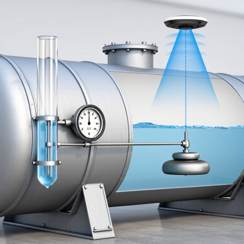
Understanding how a liquid level gauge works means looking beyond its display. A sight glass provides a direct visual reference, while a float follows the liquid surface and transfers its position to an indicator. Radar instruments calculate level from reflected signals, which can help where direct viewing is difficult. Each method has limits. Foam, buildup, vibration, and poor installation can distort readings. That caveat is easy to overlook. This guide explains common gauge types, their operating principles, and practical selection factors, so readers can assess what a reading really tells them.
What Is a Liquid Level Gauge and How Does It Work?

What a Liquid Level Gauge Measures in Tanks and Process Vessels

A liquid level gauge shows the height of liquid inside a tank or process vessel. It measures a vertical level, not volume directly. That matters. A reading of 60 percent height does not always mean the tank is 60 percent full by volume, especially when the vessel has a curved bottom or an irregular shape. A calibrated scale can help convert level into volume.

Different gauges detect that level in different ways. A sight glass lets an operator compare the liquid line with markings on the vessel. A float rises and falls with the surface, while a magnetic indicator transfers that movement to an external display. In closed vessels, pressure-based instruments can infer level from the force exerted by the liquid. The method affects what the reading means.

Operators use level readings to monitor inventory, prevent overfilling, and keep process conditions within a working range. But a gauge can show a misleading value if it is poorly positioned or affected by foam, deposits, or changing liquid density. Temperature can also alter the relationship between level and volume. A useful reading needs context: vessel geometry, liquid properties, and the gauge’s installation all matter. Small errors are easy to overlook.
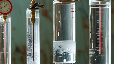
Main Gauge Types: Sight Glass, Float, Displacer, and Electronic Sensors

A liquid level gauge reveals how much fluid sits inside a tank or vessel. The right choice depends on the fluid, pressure, temperature, and visibility available. Simple, but not always obvious.

A sight glass provides a direct view through a reinforced window; operators can check the meniscus against marked graduations. It is easy to understand, though deposits or opaque fluids can hide the reading. A float gauge uses a buoyant float linked to a pointer or transmitter. As the surface rises, the float moves. A displacer works differently: a partly submerged body experiences a buoyancy change, which a mechanism converts into level. It suits some pressurized vessels, but buildup can affect readings. Electronic sensors use radar, ultrasonic pulses, or pressure to estimate level without a viewing window. Each method has limits. Installation matters.

The 2024 Level Sensor Market report from Global Market Insights estimated the global market at more than US$5 billion in 2023. That figure describes market value, not measurement accuracy, but it reflects broad industrial use. For a real selection, check the instrument’s operating range and the fluid’s properties. Foam, turbulence, and temperature shifts can complicate readings. A missed detail matters. Calibration and site testing are still worth doing.

What Is a Liquid Level Gauge and How Does It Work? - Main Gauge Types: Sight Glass, Float, Displacer, and Electronic Sensors

Gauge Type How It Works Typical Output Common Applications Advantages Limitations and Considerations
Sight Glass A transparent tube or window connects to the vessel, allowing the liquid level to be observed directly. In a connected gauge, the liquid in the glass generally rises or falls with the vessel level. Direct visual indication at the gauge. Local checks on tanks, boilers, and process vessels where the fluid and operating conditions are compatible with the glass and seals. Simple, intuitive, and does not require electrical power for basic visual indication. Requires a clear line of sight and suitable lighting. Glass, seals, and connections must be compatible with the liquid, pressure, and temperature; fouling or opaque fluid can make the level difficult to see.
Float A float rests on the liquid surface and moves as the level changes. A linkage, magnetic coupling, or other mechanism transfers that movement to an indicator, switch, or transmitter. Local indication, discrete level switching, or a continuous signal, depending on the design. Storage tanks, sumps, and vessels where the liquid can support a compatible float and the installation allows it to move freely. Uses the actual liquid surface as its reference and can provide straightforward level indication or control. Moving parts can wear, stick, or be affected by deposits, turbulence, foam, or changes in liquid properties. Float material and design must suit the fluid and operating conditions.
Displacer A partially immersed displacer experiences a buoyant force that changes as the liquid level changes. A mechanical or electronic mechanism senses the resulting force change and converts it into an indication or signal. Typically a continuous level measurement or a level-control signal. Process vessels and control applications where a robust, fixed-position sensing element is suitable. Can provide continuous measurement and is often installed in a chamber or vessel connection for process monitoring and control. Measurement depends on buoyancy, so changes in liquid density can affect the reading. Deposits, corrosion, and mechanical wear may also affect performance.
Electronic Sensors
Radar, ultrasonic, hydrostatic, or capacitance
Different technologies use different physical principles: radar measures reflected radio waves; ultrasonic sensors measure returning sound waves; hydrostatic instruments infer level from liquid pressure; capacitance sensors detect changes in electrical capacitance as the level changes. Usually a continuous electrical output for monitoring or control; some models also provide switching or digital communication. Remote monitoring and automated control of tanks, vessels, and process systems. The appropriate technology depends on the liquid, vessel, installation, and operating conditions. Can provide remote readings and integrate with control systems. Many designs have no moving parts in contact with the liquid. Performance depends on the sensing principle and installation. Foam, vapor, obstructions, changing density or dielectric properties, buildup, and vessel geometry can affect particular technologies; sensor selection and setup matter.

Selection note: The suitable gauge depends on the liquid, vessel design, required measurement range, pressure and temperature, and whether local indication, switching, or continuous remote measurement is needed.

How Hydrostatic Gauges Work: Pressure = Density × Gravity × Liquid Height

A liquid level gauge can estimate how much fluid sits in a tank by measuring pressure near its bottom. The principle is simple: Pressure = Density × Gravity × Liquid Height. In symbols, P = ρgh. A taller column creates more pressure at the sensor. Denser liquid does too. Gravity is nearly constant at a fixed location, so height can be calculated when the liquid’s density is known.

Imagine a sensor connected to a small port near the tank floor. As the level rises, the pressure on its diaphragm increases. The gauge converts that change into a level reading, often shown in units of length or as a percentage. It measures pressure, not height directly. That distinction matters. If the tank contains a liquid with changing temperature or composition, its density may shift and affect the reading. A gauge set for water could give a misleading level in a denser fluid. Not ideal.

For reliable results, the pressure connection must remain clear, and the instrument should be checked against a known level. In a vented tank, the sensor typically measures pressure relative to the surrounding air. A sealed tank may require compensation for pressure above the liquid. Installation details can be easy to overlook, especially when a tank is narrow or difficult to access. Calibration helps, but it cannot fix a poor measurement point.

Water-Column Reference: 1 m of Water Produces About 9.81 kPa

A liquid level gauge shows how much liquid is in a tank or vessel. Many gauges use a clear tube or sight window, so the liquid surface can be read directly. Simple, but useful. In a connected gauge, liquid rises to the same level as it does inside the vessel when both sides experience the same pressure.

The pressure at the bottom of a liquid column depends on its height, density, and gravity. For water, a 1-metre column produces about 9.81 kPa of gauge pressure, or pressure above the surrounding atmosphere. Two metres produce roughly 19.6 kPa. The relationship is often written as pressure equals density multiplied by gravity and height. Small changes in water temperature slightly affect density, so 9.81 kPa is a practical reference, not a universal exact reading.

This reference helps technicians compare a pressure reading with an estimated tank level. For example, a pressure sensor near the bottom of a water tank can indicate level if the liquid density is known and the sensor’s reference pressure is handled correctly. Check the installation details. Trapped air, a blocked connection, or a different liquid can distort the reading. A clean, steady meniscus is easier to read than a vibrating one, though sight gauges can still invite parallax errors. I would not trust a number without checking the actual setup.

Choosing and Installing a Gauge for Fluid, Pressure, Temperature, and Safety

What Is a Liquid Level Gauge and How Does It Work?

A liquid level gauge shows how much fluid sits inside a tank or vessel. A sight gauge displays the level through a clear tube or window. Float and magnetic designs move an indicator as the liquid rises or falls. The reading seems simple, but fluid properties matter.

Choose a gauge for the actual fluid, pressure, and temperature—not just the vessel’s usual operating conditions. Check chemical compatibility, measurement range, connection size, and visibility from the operator’s position. Hot fluid, changing pressure, foam, or deposits can affect readings. A neat installation can still mislead if the gauge is poorly matched. That detail is easy to overlook.

Tips: Follow the manufacturer’s installation instructions. Isolate and depressurize the vessel before fitting or servicing a gauge. Keep connections accessible, align the indicator for a clear view, and check for leaks during commissioning. Use suitable protective equipment and qualified personnel where hazards exist. Recheck readings against operating conditions; small discrepancies may signal buildup, blockage, or a changing process.